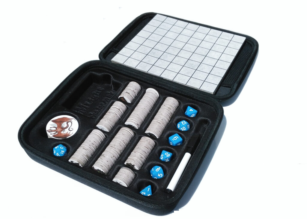
GM Light is an actual product now, rather than an idea in my head! I suppose I need to explain what it is and where it originated, well I have been a player of fantasy role playing games since I was at university in the 1980s initially as a player but very soon after, a GM. I have run many campaigns over the years and one thing that struck me was the sheer quantity of papers and paraphernalia that a GM ends up carrying to a game session. This is my attempt to reduce the amount of stuff you have to tote. Also you can bet if you roll a random encounter you won’t have the exact figure for the monster.
GM light is my solution. I have sourced 310 tokens of all the typical monsters and bad guys to allow a phys. rep. of the monster to be placed down. The numbers of the tokens lend themselves to creating a random encounter for most encounters. Rather than have a fold out battle mat which has issues with the creases and laying flat I have created two sided dry wipe tiles.
Because I wanted to cover as many role playing game systems as possible, I came up with the idea of the flavour pack. The full GM travel set comprises the GM Light core set and a flavour pack.
The flavour pack will have all the extras that are specific to a game system like monster stat cards, a combat tracker, a GM screen and a spell template. This way generic monsters from myth, folklore and popular fiction can be reused with the flavour pack for each game system.
Possible flavour packs include :
DnD 5th Edition
Pathfinder 2nd Edition
DnD 3.5
Pathfinder
Chivalry and Sorcery
Runequest
Basic Fantasy RPG
Warhammer Fantasy Roleplay 4E
King Arthur Pendragon
Middle Earth Role Playing
GURPS (Generic Universal RolePlaying System)
GM Light core could support all of them (once the appetite for GM light Core is proven) but practically, before paying for the development of flavor packs for games that may no longer be played. I need find some way to identify which are still relevant. Comments on how to poll the community please !
The GM travel kit will provide most of the reference material and game mechanics required to run a fantasy role playing game in a handy pack, significantly reducing the amount of materials required to run a session.
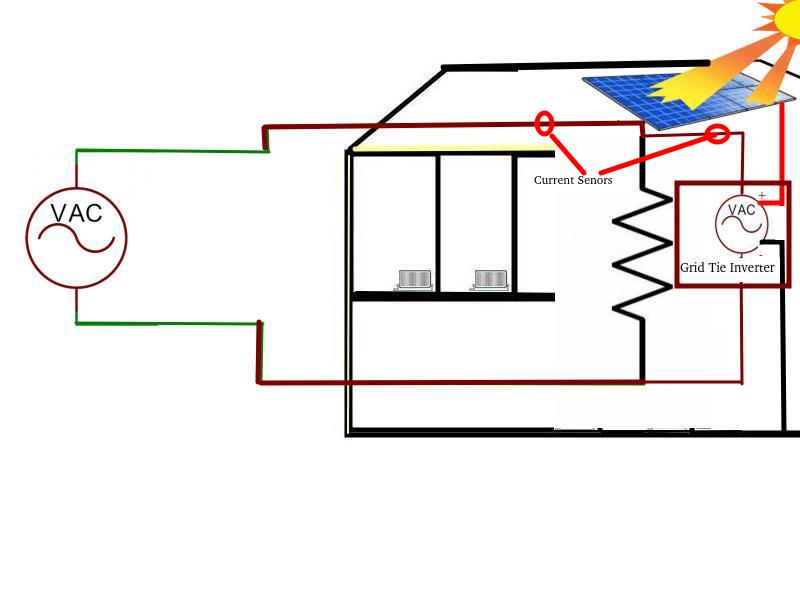
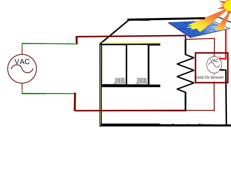
The CU monitor senses the current flow at the two points marked. It’s important to realise that even if the voltage generated by the Grid tie inverter has exactly the same peak voltage as the National Grid the current draw into the house may vary throughout the waveform because the loads in the house are not perfectly resistive and the current consumption of devices in the house will not be linear with voltage. Practically, this may result in current flowing into the house at some parts of the waveform and out at others. This means that the current at the the solar panels and the Grid tie inverter input feed will have an ambiguity, adding a safe margin ensures that current flow in or out throughout the whole of the waveform can be accounted for.
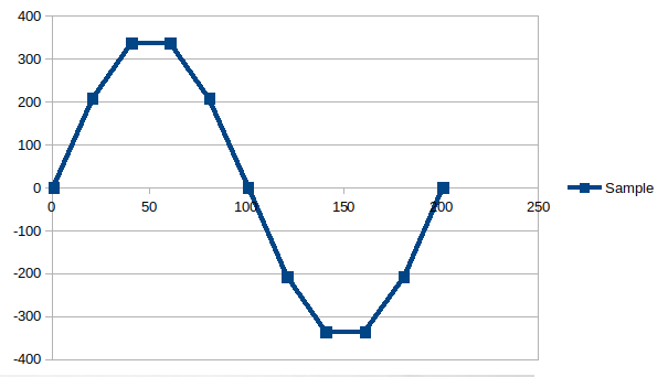
The current will be in phase with the voltage for a purely resistive load, will lead the voltage for a capacitive load and will trail for an inductive load. We need to measure the current at the sensors throughout a full cycle so this can be assessed and we can do this by sampling the current multiple times throughout the 50Hz cycle to calculate the aggregate current.
Reasonable number of samples
Each current data point sample has to be individually processed (read, scaled and logged). To give a reasonable approximation of the current flowing throughout the cycle, I insisted that a minimum of 10 samples are taken each cycle
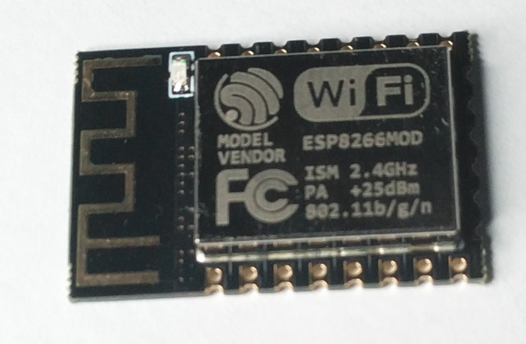
This means the sample frequency needs to be at least 500hz per channel to sample a 50Hz cycle. Both the output from the Grid tie inverter and Grid feed need to be sampled. My first design used the ESP8266 ESP01S card which was able to achieve this but the I2C bus connecting the ADS1115 to it was having problems keeping up switching between the two channels and all the other processing.
The Grid connection in my perception is the most dynamic link, potentially switching direction more times than the other sample point. I decided to over sample this link while maintaining the 500hz minimum for the Grid Tie Inverter so I started using the ESP12
This was marginally more expensive than ESP01S but provided access to a 12bit on board ADC that allowed for this oversampling.
This combination worked well but meant only one channel of the 4 Channel ADS1115 was being used.
Having two components is more costly. The cost of ADS1115 plus the cost of the ESP8266 ESP12 is more expensive than the ESP32-S2-WROOM (which supports multiple ADCs). So I have redesigned the PCB to use this processor.
The power to the house is from the National Grid and our solar panels.
240V AC mains power
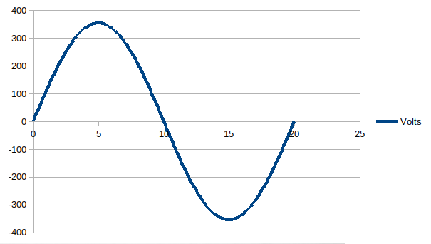
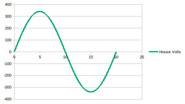
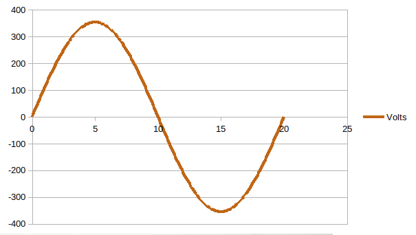
In the UK mains power is supplied from the National Grid. Alternating Current (AC) as voltage and current input is supplied as a nominal sinusoidal voltage of 240v RMS at 50 Hz with a peak to peak of about 338v. In reality this varies between 216 and 253 RMS. The voltage from the Grid goes from 0 volts to +338 volts down to -338 volts in 20 milliseconds. It repeats this 50 times a second (1000ms).
Resistive load
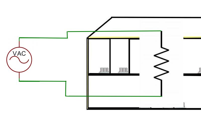
On the very simplest level a house is a resistive load. The voltage inside your house will follow a similar sinewave voltage at a slightly lower voltage because of the resistance in the wires of the Grid and inside your house.
Mains 240V AC ->
--> House Load AC
The voltage at the substation (on the Grid) will be more than that at the resistive load of the house and therefore the current will flow into the house from the Grid, through the electricity meter.
Grid tie inverter
Solar panels on the house generate electricity as Direct Current (DC). DC is fed in to a Grid tie inverter. The inverter inspects the sine wave voltage that is generated by the Grid as seen at the resistive load of the house and creates a matching sine wave voltage slightly above that of the house. This will cause current to flow from the Grid tie inverter through to the house and if there is enough power from the solar panels, out onto the Grid.
Grid <--
<-- Grid tie inverter
So the power consumption of the house will approximate to 240Volts RMS multiplied by the current into the house from the Grid plus that from the Grid tie inverter from the solar panels. Because the loads used in the house are not purely resistive this is not the whole store but it is a fairly good approximation.
Power management and current flow
To truly calculate the power usage, we would need to measure the voltage and the current profile throughout each cycle. In power management our aim is to manage the current supplied to the house so that we may use locally generated current rather than draw from the Grid. Power management rather than accurate power monitoring. Knowing the current flow is sufficient to achieve this if we also know the direction of flow. Both the Grid tie inverter and the National Grid will determine the voltage dynamically but use of the 240V RMS value will suffice to estimate power usage for our power management needs. Some electricity meters offer an LED that becomes solid lit when current is flowing out of the house and pulses when current is consumed by the house.
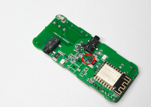
The latest PCBs for the CU monitor arrived this week. They were supposed to be the test batch to prove the release of the CU Monitors to the website. There followed a frustrating two days of soldering up and testing. Essentially I had the surface mount ADS1115 that needed to be soldered onto the board. These are tiny chips that can be tricky to solder. After soldering 3 boards I had one that worked intermittently and two that just plain failed to work. So I looked at the working one on the bus analyser and the timing of the I2C bus seemed to be causing a lot of NAKs. After tweaking the software driver, this became a lot more reliable, which suggested the bus layout on the PCB was bad! making the communication timing marginal.
This means this will not be the last board! This got me thinking. The ADS1115 is a fairly low cost 16 bit A to D converter, initially I chose this chip because it was a module that lends itself to rapid prototyping but it has 4 channels and is accessed across an I2C bus. This chip has caused me to redesign the CU Monitor PCB in the past because we are reading more than one channel rapidly it can cause significant slow down in the sample rate. Currently the CU monitor only uses one of the channels to boost the read speed. This makes this chip way over specified for our purpose.
So I intend to reassess the use of this chip and I will create a sequence of design/posts and explain my design decisions to document this procedure and help me get it straight in my mind
Web RD a simple development project aims to connect a display as cheaply as possible to the internet. This development is intended for anyone wishing to display information available online without actually requiring a separate device. The Web RD PCB is available in our store. This will allow you to build your own project without recourse to hardware design. The Web Rd development consists of :
CP2102 USB to TTL Serial Converter
WebRD PCB or Assembled WebRD Module
MAX7219 Dot matrix LED Display
USB Male to Female Extension lead
ESP8266 ESP01S
The CP2102 is a low cost stable and reliable way to connect a project to the power providing both 5V and 3.3v outputs. I’ve run them for thousands of hours with no problem. Powering a Project can can be an issue. This piece of test gear does the trick nicely.
The MAX7219 Dot matrix LED display is the low cost way to display large text.
The ESP8266 ESP01S is a very capable processor that provides plenty of processing power and a very cost-effective way of connecting to the internet.
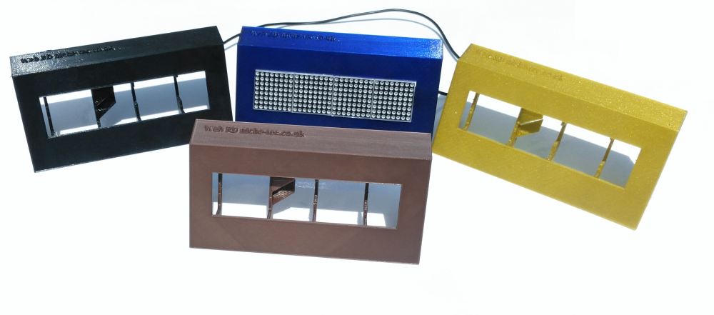
We have available in our store 3d printed enclosures that provide housing for the display available in a mixture of colours
There are many use cases that make use of the Web Rd