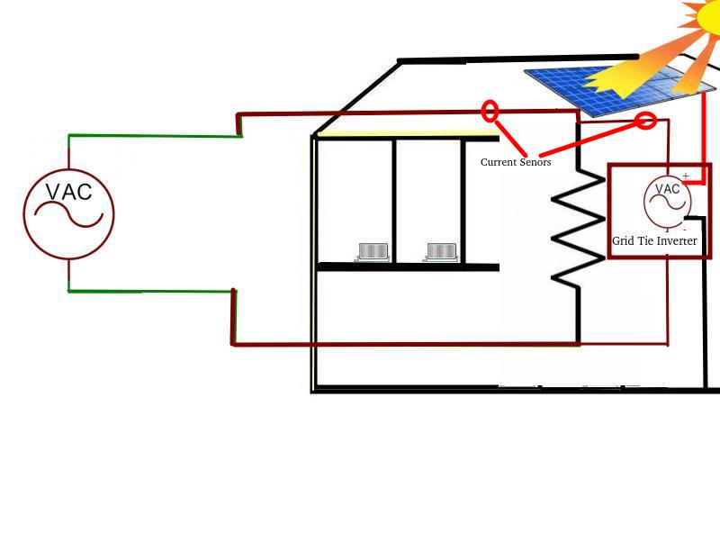
The CU monitor senses the current flow at the two points marked. It’s important to realise that even if the voltage generated by the Grid tie inverter has exactly the same peak voltage as the National Grid the current draw into the house may vary throughout the waveform because the loads in the house are not perfectly resistive and the current consumption of devices in the house will not be linear with voltage. Practically, this may result in current flowing into the house at some parts of the waveform and out at others. This means that the current at the the solar panels and the Grid tie inverter input feed will have an ambiguity, adding a safe margin ensures that current flow in or out throughout the whole of the waveform can be accounted for.
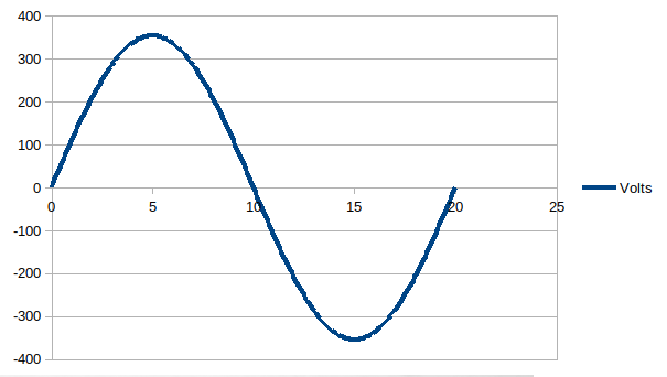
The current will be in phase with the voltage for a purely resistive load, will lead the voltage for a capacitive load and will trail for an inductive load. We need to measure the current at the sensors throughout a full cycle so this can be assessed and we can do this by sampling the current multiple times throughout the 50Hz cycle to calculate the aggregate current.
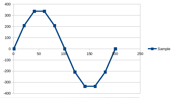
Reasonable number of samples
Each current data point sample has to be individually processed (read, scaled and logged). To give a reasonable approximation of the current flowing throughout the cycle, I insisted that a minimum of 10 samples are taken each cycle
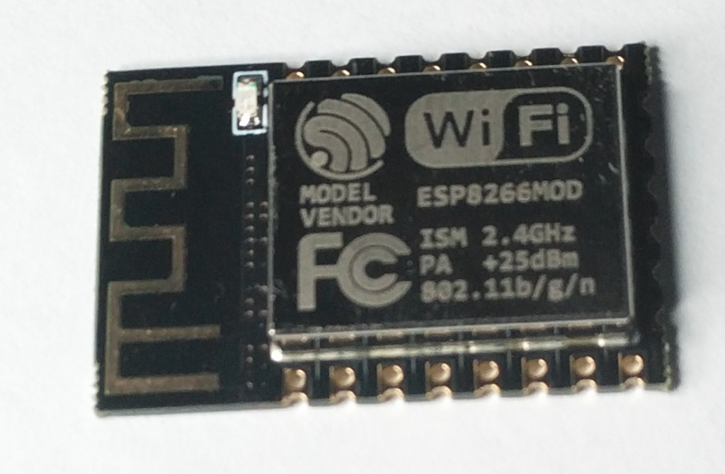
This means the sample frequency needs to be at least 500hz per channel to sample a 50Hz cycle. Both the output from the Grid tie inverter and Grid feed need to be sampled. My first design used the ESP8266 ESP01S card which was able to achieve this but the I2C bus connecting the ADS1115 to it was having problems keeping up switching between the two channels and all the other processing.
The Grid connection in my perception is the most dynamic link, potentially switching direction more times than the other sample point. I decided to over sample this link while maintaining the 500hz minimum for the Grid Tie Inverter so I started using the ESP12
This was marginally more expensive than ESP01S but provided access to a 12bit on board ADC that allowed for this oversampling.
This combination worked well but meant only one channel of the 4 Channel ADS1115 was being used.
Having two components is more costly. The cost of ADS1115 plus the cost of the ESP8266 ESP12 is more expensive than the ESP32-S2-WROOM (which supports multiple ADCs). So I have redesigned the PCB to use this processor.