The CUMon Logs have been taken off line whilst the new Energy diverter is developed.
Development Notes
The current software that has been developed with CUMon measures Current magnitude and does not need to worry about the current phase because it determines export and imports by cross-correlating the PV amplitude with the Grid Connection amplitude.
Inverters and CT coils
Inverters use CT coils or Modbus meters on their Grid Connections to determine the power flow to or from the the Grid
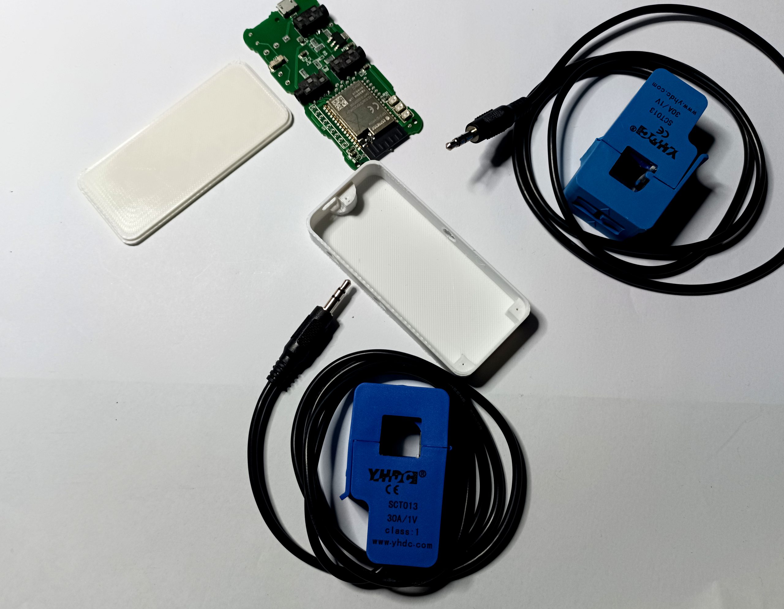
CT Coils can only measure current amplitude. You do not know the phase angle of that current . To measure whether the current is flowing in or out of your house you need a Voltage value to combine with the Amplitude value from the CT coil. With Normal Grid AC to an inverter you can combine the CT Amplitude with a Voltage reading to calculate this.
With CUMon we work with a CT coil that just requires to be clipped into the Grid AC connection and the orientation of the CT coil is not needed to be known because the Current flow is determined by the Cross Correlation to the PV current.
We have chosen an inverter that has a Modbus meter replacement option that allows an NRGDivert module to mimic the Modbus meter and control how the inverter perceives the virtual “Grid connection” and thus control whether power is diverted to battery or to house/Grid.
Progress so far
We have successfully interfaced with Modus on the Inverter and have been able to control the Flow of power in and Out
We have used a very basic control loop to divert energy to the battery
We have supplied the house with power from the battery
Notes
The inverter can be set in Charge the battery mode or charge Or power the House Mode
The MODBUS meter supplies a varied interface with lots of data available but the Inverter only seems to read the bare minimum 3 registers of Reactive power
Problems
We have to emulate reactive power and this is currently unknown by CUMon
We have a control loop that is basic and gets lost easily
The inverter “remembers” the power output state and continues to drive this even if the control loop fails
Conclusion
The process is possible and the concept has been proven with an engineering setup. The Control loop needs work but is feasible
So if you have been watching our Logs for the last month you might be concerned that the NRGDivert has Stopped or failed ! well the problem was the our Hosting service provider changed servers on us and replaced the server software with a different package. This caused massive failure of the logging.Logs between the 24th or April and 2nd of June were Broken and should be ignored. We hopefully have resolved this now so from the 2nd of June Logs are good again. We appologise for any confusion and misdirections.
The Logs are left in place for Recording Keeping purposes Only.
The development changing the logging has resulted in a faster and more secure and robust logging process.
Starting in March 2024 we are giving away to the first 5 applicates that meet the criteria and ask to join a full NRGDivert setup
This system was developed to divert excess PV electrical power to a local energy sink rather than exporting it back to the grid. The original test bed setup is being enhanced by adding Solar battery storage and the excess energy use case will therefore change. We will continue to support this system but without a suitable test bed we cannot show/prove it continues to work. So you will need to agree to performing as an anonymous test bed and have a suitable setup to qualify.
What is needed to Divert usable energy to a Battery ?
Assuming that the Voltage of the Battery is 48V. We need at least this voltage to Charge it.
If we are going to use make domestic use of this Battery power we will need an inverter.
Scope of this Development
The scope of diverting energy from an existing Solar PV setup to a Battery and making use of that energy is daunting ! Being at the scale of a full PV System just without the actual Panels. So we are left with the practical problem of how much of a Home Generation system we need to duplicate !
Possible approaches
Use NRGDivert to create a 48v Compatible Charger for the Battery
Find Component subsystems to Interface CUMon to and then program them.
??
Arguments and Reasoning
Regarding 1 above the simplest approach is to transform the diverted power,rectify and stabilise it.This works to fill the Battery however does not then provide a solution to make use of this power. The problem of providing the energy back into a domestic environment is that this is constrained by a plethora of regulations any Niche-tec system would have to comply with.
In the case of 2 above we would need standalone systems to work as our subsystems.
So we are looking to energy divert using a Hybrid inverter. This will ensure the existing PV system remains inviolate and allow the add on system to be stand alone. This perhaps marginalises the usabilitiy of the system for other developers.
Development Description
The aim of the development therefore is to emulate a CT (Current Transformer sensor) to interface back to a hybrid inverter and that way control the charge and discharge of the battery on the new inverter. This emulation to be completely digital by emulation of the RS485 Modbus Protocol.
This limits the scope of the development to a manageable and achievable goal. Removes the Legal/regulation conformity and produces a system that diverts Excess Solar into a Battery. Furthermore a WIFI CT RS485 Device could find other applications.